The choice for QRP 20m assisted is obvious. There has never been a entry in this section from the Netherlands. It is possible to get a dutch record again....although after checking log submissions I see PA2REH did submit in the same section. Some competition is nice....
My goal was 100 QSOs. I had less time saturday end only able to make 30 QSOs on that day, surprisingly most with USA. I had some more time sunday ended with 108 QSO in the log. Of course no real DX with QRP......although! Late in the afternoon at sunday I noticed some fluttering signals on the band, that means signals from the north. And yes, after several QSOs into zone 4 I finally managed to get K2PO from Oregon (zone 3) into the log. I consider that DX for shure, 5W CW into a inverted-V remember!
The map is just a indication. The Oregon contact is not on it. This is because the locator is not known by the software of course. I was really surprised I could work so many from the USA. Some of those contest stations really have good ears...
Palstar AT1KM 1:4 ruthroff balun compared with homemade 1:1 current baluns outside the tuner. The goal is a practical comparisation between these baluns. I made two 1:1 current baluns specified to the instructions from G3TXQ, A useful article can be read here:
A tuner balun is made with bifilair windings since it doesn't need to have a 50 Ohm impedance and unwanted impedances can be tuned out besides that it can withstand higher differential-mode voltages.
I took the design for the low bands and higher bands. 17 windings on two FT240-43 ferrite rings for the low bands and 9 windings on three FT240-52 for higher bands. To keep the rings together I wind ptfe tape on it first. I decided to wind the ptfe wires in ptfe tape as well to keep them as close together as possible.
Balun under test
The FT240 ferrite rings were bought from fellow blogger PA3HHO who has a lot of info about antennas and HF transformators/chokes on his blog.
The baluns are doing a excellent job balancing. Though, is it really better as the internal 1:4 balun inside the AT1KM?
My RF current indication meters are having a scale from 0-100% and a little more. Good enough to compare. A test was made with 50W FM input.
Band
%Left
1:4
%Right
%Left
1:1 LB
%Right
%Left
1:1 HB
%Right
80
60
60
60
55
60
60
60
20
70
35
25
30
30
40
110
110
110
110
110
110
30
105
110
110
110
110
110
20
80
68
70
70
70
68
17
110
110
110
105
110
110
15
70
80
70
70
70
68
I didn't test the 160/12/10m. The 2x20m inverted-V isn't really efficient for those bands and so it isn't really interesting.
For me most interesting is my favourite 60m band. It is clearly not in balance with the internal 1:4 balun. But is with the 1:1 baluns. However I expected higher currents, not only on 60m but on the other bands as well. Interesting to see that balance on other bands is almost equal. Overall you don't see much difference at all. The internal 1:4 balun gives some more current on 20m and 15m. Actually I didn't expect this outcome of this comparisation, The Palstar AT1KM performs much better as expected, even with the 1:4 ruthroff balun inside.
On the right you see the baluns. The boxed one is made for the higher HF bands and designed to fit below my multiband vertical between the CG3000 autotuner and the antenna. It doesn't feature any PL connector, only terminals.
I really do not expect any change in signal strength with all baluns. I also monitored noise on receive. It is all the same as soon as I tuned to a 1:1 SWR. Theoretically common mode surpression and balance would be a lot better with the 1:1 baluns and many articles describe much more current output. However in the "real" world I don't see much difference.
I have to write though that I don't have that good measuring equipment of course. Others will read this and tell me I should use certified and calibrated equipment. I don't have the money for such gear and I like to build these things myself. I don't know how much the outcome would differ except for some real current numbers in ampere instead a 0-100% scale. Besides that I measured it on my inverted-V which can differ from other antennas and environments. There are so many variables that can have a influence that I can't write if I'm right with this practical balun test.
I own a discontinued Palstar AT1KM. I consider Palstar as one of the best antennatuner builders. The tuners are expensive but quality is very good. It works fine, actually I never had troubles with it and tuning is very easy. However, in the past even antennatuner builders had it wrong.
A while ago a began to read about baluns and what they do. I read several tests with baluns at the output of a unbalanced tuner since I was unshure if I should use a 1:4 or a 1:1 balun behind my CG3000 autotuner to feed my vertical. I did some experiments myself and continued to read all about it. Now finally I read a article in a Dutch amateurradio magazine called Razzies about baluns that was a real eye opener. It contained a test with a voltage, current and no balun with both coax and open line. The winner was clearly the current balun in all cases.
Now, I was thinking....
On the back of a Palstar tuner the balun instructions
Inside the AT1KM is a 1:4 ruthroff voltage balun for balanced output, I guess it was kind of a standard about 10-15 years ago. My MFJ948 also had a 1:4 voltage balun inside. But with the knowledge of today it seems it is not the right choice to make. I was curious if Palstar is still using a ruthroff balun inside their tuner. If I look at the AT-500 the specs tell me they are using a 1:4 current balun, though if I look on the photo it looks like the ruthroff balun in my AT1KM. Two other tuners they make don't have baluns inside anymore. Baluns are now available in a non conductive housing which should be connected with the shortest possible coax to the tuner. the reason: baluns mounted against a metal chassis are subjected to mutual capacitance, which may also disturb the balance. It is simply better to mount them externally in a plastic box (Owen Duffy, VK1OD). The Palstar engineers listened well...
Actually the same Owen Duffy came to a conclusion: "A unbalanced T match followed by a 1:1 Guanella (current) balun in an external non conductive enclosure and having high choking impedance, very short coax connection to the ATU, and high voltage withstand is capable of excellent performance in a ‘balanced ATU’ role for general purpose HF application."
...Exceptions are the heavier Palstar AT4K and AT5K manual tuners which have a 1:1 balun at the input and mounted inside the tuner housing but not against the housing. At first I though, why not? What difference would it make. This is what W8JI tells about it: "Any article that claims placing a current balun at an unbalanced tuner input helps balance, or generally helps the balun work better, unfortunately is mistaken. Moving the current or choke balun to the input of an unbalanced network makes balance much worse on higher bands, and does not help lower bands".
It is unclear to me why Palstar engineers did choose such a configuration with high power manual tuners anyway? The risk of destroying a 1:1 balun with high power is very high anyway.
So, how to make your T-match tuner work better? Is it that simple? Yes it is....don't replace those 1:4 ruthroff baluns in your old tuner. Let them be. Just make the best current balun you can, place them in a plastic box and connect them with a short as possible coax to your tuner to feed a open line to your antenna. Does it really help? Well, it depends how you antenna is configured I guess. But if you want to feed a open line to you antenna it is just as easy as connecting a good quality 1:1 current balun between the tuner and the open line. You don't have to buy a expensive balanced tuner or a tuner that has a balun inside.
Will we have different thoughts about this subject in the future? 20 years ago it was common to place a 1:4 balun inside the housing of a antenna tuner, most of us didn't have the equipment to verify if this was working right. With the decreasing prices of specialized measuring equipment confirming that your gear is working well is in everyones reach.
This is a dutch language contest, however open for international traffic. But since the content is only interesting for the dutch I'll write it in dutch for archive purposes.
Foto rechts: Vanuit de radioshack. Dat grote gebouw op de achtergrond is de originele "rode" school. Er was een station die er aan twijfelde. Uiteraard word het gebouw niet meer als school gebruikt. Overigens is het maar de vraag of de naam "Roodeschool" van deze school afstamt.
Voor mij is dit de leukste nederlandstalige contest van het jaar. Het speelt zich alleen af op de 80m band en dus de bereikbaarheid van Nederland is meestal prima.
Het leukst is natuurlijk het speuren naar de 12 steden/dorpen die mee tellen als multiplier. Of dat lukt is altijd de vraag. Sommige multipliers zijn maar een korte tijd aanwezig. Als je ze mist heb je pech. En dat had ik deze keer. Ondanks dat alle 12 multipliers aanwezig waren heb ik Harlingen wel gehoord maar niet kunnen werken en Bolsward helemaal niet gehoord. Nou heb ik wel heel relaxed mee gedaan en hier en daar een praatje gemaakt, want daar is deze contest ook een beetje voor bedoeld. Maar misschien was ik wel een beetje te relaxed. Denk dat de beste strategie is om elke 15 minuten ook even de band over te draaien om multipliers te zoeken. Ik heb dat wel een paar keer gedaan maar ook best veel CQ geroepen. Dus maar 10 multipliers....nou ja het geeft niet. Ik heb een hoop plezier gehad en een hoop bekenden gehoord en gewerkt. De vreemdste plaatsnaam voor mij was toch wel de QTH van PE0JXA/P die bij het haventje van Oude Zeug stond. Ik hoorde een aantal andere stations ook worstelen met deze plaatsnaam en had er zelf ook nog nooit van gehoord. Tja, dat zijn leuke dingen die gebeuren vind ik en je leert ook nog wat. Even opzoeken, waar ligt dit plaatsje:
Als ik zelf in die situatie zou staan had ik toch gekozen voor de plaatsnaam Kreileroord. Maar goed, bijzonder is het wel.
Het was alles bij elkaar weer een bijzonder leuke en gezellige contest. Ik bedank de organisatie, want die krijgen het toch elk jaar weer voor elkaar. Tot volgend jaar!
Hierbij nog een korte video opname. Met o.a. PA2LO, PA3MM, PA7MM, PA0Q en PA3JD. Ik had nog meer op willen nemen maar achteraf waren het alleen foto's en geen video.
For future experiments and the one done recently I really need a antenna current meter. Best is something that shows the balance as well since that is one of the features a S-match offers. Another thing you can measure of course is the RF current which should be as high as possible. That way it's possibible to compare antennatuners on open line.
PA0FRI has a good design on his site. Components are not really critical as long as they are the same for both lines.
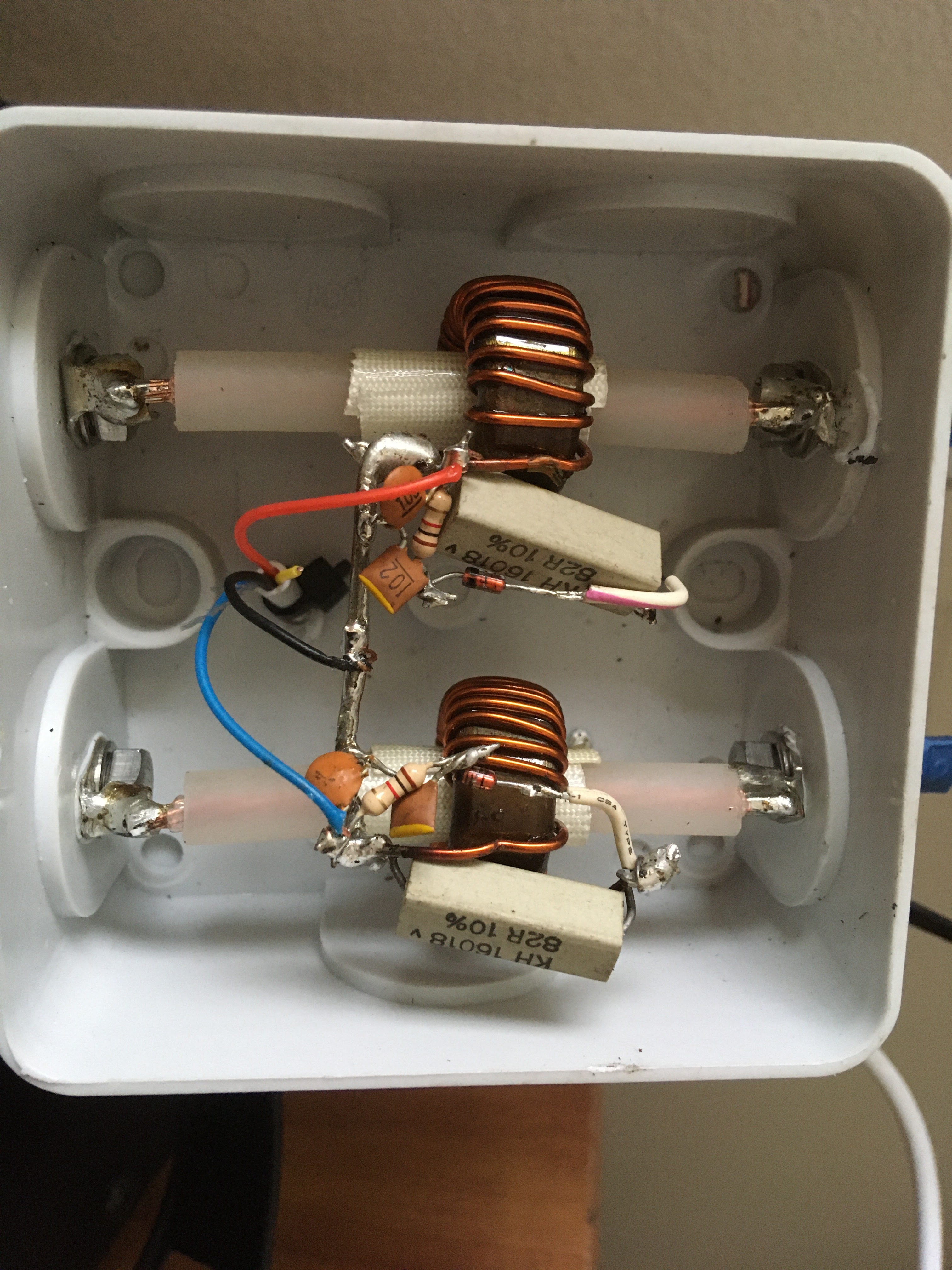
As a real amateur experimenter I first look around in my scrap box for parts. It took a while but I found everything except the plastic boxes to build everything in. Some soldering and fitting....this is the result:
Frits does use T80-2 torroids with 25 windings. I found two pre winded ones in my scrapbox, 23 windings on a unknown torroid. The big 2W resistors should be 50 Ohm, other designs show 100 Ohm. I found two indentical 82 Ohm resistors that will do the task. For meters I found a nice AKAI VU meter combo I salvaged from a AKAI cassette player. It took me some research to find out these are microA meters, just what I needed.
Because I didn't know if it would work well I decided I would not build the meters in a box yet.
Basically this is bare system. It actually works better as expected so I'll continue to make it look nice in some time.
Now, I was very curious about my antenna system (2x 20m inverted-V "doublet") balance...first test on 10m behind the S-match tuner shows a reasonable balance. It's not perfect but close, nothing is perfect in the real world.
On 20m, the system behind the S-match is almost perfect in balance.
However.....
Left is 50W on 60m with the Palstar AT1KM (with 1:4 ruthroff balun inside).
Right is 50W on 60m with the S-match.
It clearly shows a unbalance with the Palstar, the S-match does a fine job in balancing.
I can show more pictures but it is not necessary I think. Other bands all showed the current in balance. I also tested with the Palstar, except 60m all other bands had a balanced current on the open line.
Well, I finally managed to get the meters in a box...
The tiny lightbulb lighting in this combo was still intact. Wow, it looks pretty nice...
Scrap parts remember! It looks very professional after all...
I can assure you this was not an easy one. Very weak signals from this Russian DXpedition in Malawi on their last day active. I did receive them yesterday but there was unfortunately a birdie on their frequency and too many that made a call. After almost endless trying I finally made a QSO.
Some strange things were noticed by me and fellow 60m DXer DB6LL. 7Q7RU made CQs while many were calling like they didn't receive anything?? Hartmut noticed that they also responded to stations below 1000Hz in F/H mode, even to stations calling on their frequency. Normally that is not possible in WSJT-X. So we think they make use of alternative software. We could be mistaken of course? Anyway, it doesn't matter, they did an excellent job in these difficult times...
Might rename this post hypocrisy. Yes, against my QSL policy I payed for this QSL from the only HAM/radioamateur that is active from Somalia. At least Ali is honest on his QRZ page, he needs extra money to maintain his station and keep going on with activities from this DXCC. I still had some US dollars which have been stored for over 20 years in a envelope. The last time I spend dollars for a QSL was when I still collected QSL from 11m (CB) DX contacts. I thought this time it was well spend. Paper QSL is something that will slowly extinghuish in the next decades I think, so this might be extra special.
What got my attention is that he works with a Little Tarheel 2 mobile antenna. This is a motorized screwdriver mobile antenna. Not shure if he mounted this on a car or on anything other metal for counterpoise. Or he might have installed a radial network? Although not QRP I think this is still a amazing contact.
July this year I worked Svalbard on 6m I worked that same station from Svalbard on 60m already last year. But this time JX2US from Jan Mayen is on air. It was just waiting till it showed up on 60m. Luckely the HamAlert app does help. I received a spot this evening and immidiatly logged in remote into my station which was already ready and listening on 60m FT8. A few minutes later I was in the log!
Svalbard is discovered by the dutch, Jan Mayen is discovered probabely by a Irish monk and also it is claimed vikings landed on the island. It was rediscovered and documented by fellow dutchman Jan Jacobszoon May van Schellinkhout (Jan Mayen) in 1614. The dutch were pretty good in discovering I guess ;-). Interesting facts can be found on the wiki page.
This is a dutch language contest, however open for international traffic. But since the content is only interesting for the dutch I'll write it in dutch for archive purposes.
Event: PA-beker contest SSB 2020 Section: high power Logger: N1MM+ Station: Icom IC-7300 100W Antenna: Inverted-V apex 12m
Dit jaar geen antenne experiment. Ik heb de antenne nog wel liggen. Maar gezien de resultaten van vorig jaar heb ik mijn twijfels of het echt veel uitmaakt voor de uiteindelijke score. De 40m MUF moet gewoon boven de 7,1 MHz liggen voor 100-400km. Zo niet dan maakt vermogen of een speciale antenne niet veel uit. En ligt de MUF wel hoger dan doet de 2x20m inverted-V het ook prima.
Strategie
Een vrije frequentie zoeken op een rustig deel van de 80m band. Dat is dus in het gedeelte tussen 3,600 en 3,650 MHz. Dan gewoon een uur CQ roepen (runnen) daarna de band afzoeken of er nog stations zijn die ik niet gewerkt heb. De MUF goed in de gaten houden en dan rond 11 uur lokale tijd een rondje 40m doen. Daar bij voorkeur onder de 7,1 MHz blijven vanwege de novice station die meedoen. Als er dan stations gehoord worden bij voorkeur zelf weer gaan roepen en dan maar hopen dat er wat stations reageren. Rond 12 uur lokale tijd beslissen om op 40 te blijven of om weer terug te gaan naar 80, dat is de moeilijkste keuze en kan beslissend zijn voor de eindscore.
De contest
Ik begon niet precies om 10 uur maar wat later. Dat maakt op zich niet zoveel uit denk ik. Wel als je een half uur later begint. Maar dit was hooguit een 10 minuten late start. Ik ben eerst maar eens op zoek gegaan naar een rustige plek ondertussen een paar stations gewerkt. Daarna een uur zitten roepen met best redelijk aanbod. Heb een deel opgenomen via de webSDR van Twente om later te evalueren. Rond een uur of 11 even snel de hele 80m band gezocht naar stations die ik nog niet gewerkt had, dat waren er weinig. Ik zag ondertussen de MUF al omhoog gaan en dus maar naar 40m gegaan. Daar hoorde ik heel zwak een paar stations waarvan ik sommigen met moeite kon werken. Op gegeven moment toch maar tegen wil en dank een plek gezocht om te roepen. Daar kwamen verrassend genoeg wel een stuk of wat stations op terug. Ik dacht dat de MUF maar rond de 6,4 MHz was....maar toen ik nog een keer keek was het plaatje net ververst en zag ik dat de MUF zeer gunstig was.
Maar helaas had ik het idee dat veel stations het niet door hadden. Want veel respons kreeg ik daarna niet meer op mijn roepen. Dus maar weer de band op en neer om te zoeken met wisselend resultaat. Het ene moment hoor je stations sterk en het ander moment zijn ze weer weg. Een aantal stations had blijkbaar ook veel last van QRM want ik werd echt niet gehoord. Alles bij elkaar heb ik misschien te lang op 40m door blijven roepen met als resultaat wel 25 QSO's en 18 multies. 10 minuten voor de contest afliep ben ik weer gaan zoeken en roepen op 80m, dat bracht nog wel wat QSO's op. Ik had denk ik beter wat vroeger terug moeten keren naar 80m. De vraag is of ik dan nog wat extra multipliers en station's had kunnen werken, meer als op 40m? Het blijft natuurlijk een uitdaging. Jammer is ook dat je met 100W gelijk in de high power sectie terecht komt. De stations die boven aan de scorelijst staan werken naar alle waarschijnlijkheid alle met 400W (of meer ;-) ).
Doelen
Doelen stellen in deze contest is moeilijk. Het geheel hangt af van de condities op 40m. En die zijn moeilijk te voorspellen. Het klinkt gek maar mijn doel was om PA0Q Hans te werken op beide banden. Ik weet dat Hans verhuist is en had hem na zijn verhuizing niet meer gesproken. Ik vernam al dat hij een horizontale loop had hangen, zoiets heb ik ook jaren gebruikt. Ik heb Hans op beide banden kunnen werken, dus doel gehaald. Voor de rest heb ik natuurlijk genoten van alle nederlandse signalen, sommige hard en sommige wat zwakker. Helaas heb ik één station gemist en ook niet gehoord, dat was PA3JD Joop uit Dedemsvaart die ik eigenlijk altijd wel werk in deze contest. Helaas....volgend jaar beter... Het was een gezellige contest, tot volgend jaar...
Actually I thought I did work Bonaire PJ4 before. Probabely because I worked PJ4 so many times. But checking my 60m DXCC list this is definitely a new one for me. Received him yesterday morning with excellent signals but was not in the shack at that time. This morning I woke up early especially to work PJ4/DL6KR. It was an easy one...
My last post about the MFJ948 T-match tuner conversion to S-match tuner dates from February this year. It contained a fault which was quickly seen by PA0VAJ Jan. I asked the readers if they could discover the fault but it seems no one was really interested or it was too difficult to find. Or readers might have expected I would write about it in a short time. But actually I had other things on my mind and the tuner was put in a carton box for later experimenting.
The fault
The MFJ989 to S-match conversion diagram from PA0FRI's page contains a fault. It is there since 2018 and I don't think anyone has noticed. Probabely no one else has tried to convert a T-match to S-match yet. The coil and capacitor(s) need to be on both sides of the two 8 winding sections. In this diagram the coil is mounted over the 16 winding part.
The strange thing is that the same page does show the correct diagram at the top. I didn't see the difference at first till Jan told me the wiring was incorrect. So, I changed it to correct things.
The problem
After changing the wiring testing showed a little better SWR but still most frequenties couldn't be tuned exactly to 50 Ohm. The problem is the switchable coil. PA0FRI noted this as well and so I changed the wiring again to make a quasi roller inductor. This is done by connecting a varco in series with the coil. Unfortunately the PA0FRI site contains another fault which was easy to see...
Obviously I guess readers of this blog will see this fault instantly.
The result
Much better! I'm finally able to tune 1:1 on most bands from 3,5-30MHz. Except 15m, for that band I need to switch extra capacity over te main capacitor C2. For 80m it helps as well to get a slightly better SWR. For 60m I need to connect the antenna over de coil, it will not tune when connected over the capacitor. Tuning is pretty difficult since the components in the MFJ-948 are small. I remember it was difficult to tune when it still was a T-match tuner as well. Without a antenna analyzer like the MFJ-948 I use it is almost impossible to find the right settings.
For archive purposes this is my list of settings:
S-match test
Over LOver C
Band
C1
L
C2
C1
L
C2
80*
8
K
5,5
6
L
1,5
60
3,75
K
0
np
np
np
40
2
J
12
-3,5
L
-3,5
30
1
I
-5
-3
F
-2
20
0,5
H
-3
-1
F
-1
17
2
E
-3
0
E
-2
15*
10,5
L
7
np
np
np
12
1
I
9,5
2,5
E
-2
10
9,5
H
-1
I
C
-4
np=not possible
* with 300pF C parallel over C2
Now, the S-match tuner seems to be excellent to balance your transmission line. But is it efficient? I think that depends on what components you use. The MFJ-948 components are not that great...
To determine the quality of the build and compare it with my Palstar AT1KM I should build a RF antennacurrent meter first. More about that later...
It has been quite a while ago I saw or heard a 60m band new one. At least 9J2BS has been active before on this band but not very often. I finally had the chance to work him.
Once and a while I participate in a UKEICC 80m SSB contest which is a one hour contest with very fast publication of results. I wrote about this before a couple of times. It is really fun and great for practising or developing contest strategies.
There is a change this year, the exchange is no longer a 4 digit locator (JO33 for me) but 6 digits. It's a longer exchange but calculating the distances is more precise and fairer. In this contest accurate logging is important, penalties are given for wrong logging.
It is fun if you win of course, but since most participants are from the UK and Ireland someone from Germany, Sweden or even Lithuania does clearly have an advantage. In the Netherlands we're simply too close. However, for me it is not important to win. I just want to test my abilities and experiment with new ideas which I can use in other contests.
This time I was thinking about the spectrum display I use in N1MM+, it is excellent and a great advantage you have with a SDR receiver. You easily find a nice quiet spot on the band to give CQ and see were other stations are. But of course, finding such a quiet spot can't tell you if it is quiet in the DXCC you want to reach. Since most of the participant are in the UK I thought to find a SDR in the UK to see if I was transmitting on a quiet part of the band without much QRM and splatter, I did choose RAF hackgreenSDR in Nantwich, UK to listen/view.
Above the N1MM+ contestsoftware. At the left you see the spectrum display from the webSDR on top, below is my own from the IC-7300. As you can see my signal was quite strong in the UK. That will say, till 20:30 it was, then it vanished and I didn't see it again. Immidiatly noticed my QSO rate dropped dramatically. Whatever antenna you use or how much power, it doesn't matter you see. If there is no propagation it's over....
The second experiment, something I do most of the time with unique exchanges is repeat the exchange I receive. I repeated every locator I heard to be shure I was logging the right exchange.
The nice thing is that every participant gets a nice report next day with results and more info like faults you make, penalties etc. This is called a UBN report which stands for Unique, Busted, Not In Log.
This was my report partly (I removed the complete log).
Assisted: NON-ASSISTED Power: Low Callsign: PE4BAS Operator: PE4BAS Locator: JO33JK Total QSOs: 47 Potential Points: 147 Actual points: 147.00 Points per QSO: 3.13 Longest scoring QSO: 2251.12 km with UT2II Highest points QSO: 6.00 points with LY4ZZ
DUPES _____ No Dupes!
NIL ____ No NILs!
Busted reports ______________ No busted reports!
Busted Calls ____________ No busted calls!
You see, it helps when you double check. No faults. I obtained 4th place in my section in the end. Well actually 3rd, a shared place with DL2SWR. I don't care actually, I had fun. The two things I wanted to try worked out well.
Fair enough it looks easy to reproduce. This looked like a very easy and fun experiment, but is it that simple?
I built my first version with 2 RVS bolts about 4 cm spaced and about 4 cm in the water mixed with a spoon of baking powder. It didn't work out, the SWR was 1:5. So, I tried another spoon with baking powder, nothing changed. I did remove some of the water, nothing changed. So I guessed the size en the length of the electrodes could be important. Or it might be the amount of water? Or even the amount of power? Joe WB9SBD didn't mention anything about it.
So, I decided to write Joe an e-mail to ask for the size of his electrodes and the amount of baking soda. He told me the electrodes were made of #14ga wire, 5" long and about 4" was in the water. Spacing is about 1". I quickly converted it to metric. Normal electrical installation wire with removed isolation is about 2mm thick, they should be about 13 cm long and about 10 cm should be in the water. A theaspoon of baking powder mixed with water is more as enough. I took a big 1000gr. peanutbutter jar and mounted everything the right size. However, although a exact copy from Joe his experiment he already uses for 10 years, the SWR was now still 1:3! Is it a difference of dutch water compared to water in the USA? Is it a different kind of baking powder? Or may be the wire diameter or material has influence? So, just to experiment I pulled the electrodes out of the water to see what happens? And now, indeed I see the SWR going to almost 1:1. I removed some of the water until I finally had a reasonable SWR from 160m-10m. But now the electrodes are about 1 cm (0,4") in the water, actually they just dip into the water.
I also checked the dummyload with the MFJ259 analyzer. It shows 52 Ohms from 1,8 to 14 MHz, but then it's rising till 88 Ohms on 29 MHz. Joe did have a complete different experience with good SWR till 180 MHz!!
Well, this was a nice experiment but not 100% reproducable. There are some variables that seems to have a influence.
- electrode wire material?
- electrode wire diameter?
- electrode length?
- electrode spacing?
- Water difference?
- Bicarbonate difference?
- Amount of bicarbonate
- Length and type of coax?
In the video I like to say "sodium bicarbonate". It's the same as natrium bicarbonate or bicarbonate. baking powder, baking soda. Some will say baking soda is three times stronger as baking powder?
If anyone likes to try this experiment, let us know what you discovered.
Update 06-Nov.-2020: Joe did write me an e-mail about the difference between baking soda and baking powder. Someone else did comment on the post with the same outcome.
Baking SODA and Baking POWDER are totally different chemicals.
I do not know what POWDER's properties are.
Soda is
NaHCO3. It is a salt composed of a sodium cation (Na+) and a bicarbonate anion (HCO3−)
Powder is,
Part Baking Soda, but also some sort of an acid and a buffer of most times corn starch.
So the extra ingredients of the powder might be messing with the Ions,
Also if you started with a teaspoon worth you may have gone below 50 ohms at first try.
what is the SWR and impedance of just plain water?
Then add just a tiny bit of actual SODA, mix well till 100% dissolved, and let it "Rest" for say 5 minutes so the SODA fully mixes with the water. Then test and see how things moved compared to the plain water.
Joe WB9SBD
Interesting, so there is at least a difference. I will take his advice and see what SWR of plain water is. Then add small bits of baking soda to see what it does.
To be honest, what is good propagation? I didn't have much time for radio today, other chores took my time. But the time I had available for radio was pure quality. Made QSOs with Australia, Pakistan, Indonesia, South Africa en Argentina on 10m.
If you look at the propagation numbers:
According to this 10m is "poor". But we still make worldwide contacts on 10m these days. However, I turned the VFO a few times to listen to the CW/SSB part of the band. I even checked the 11m band. But even with the 10m FT8 frequency full of DX signals nothing was heard on CW/SSB...